![]()
![]()
![]()
![]()
![]()
![]()

![]()
![]()
![]()
![]()
![]()
|
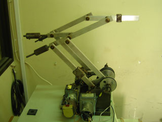
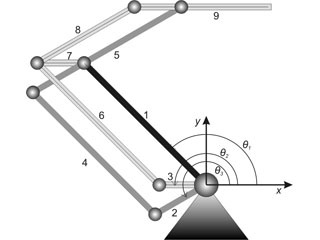
The Robotic Arm Case-Study Introduction
Actuators:
3 dc motors
located at the base of the arm are used to actuate the robotic arm. This robotic arm was developed in the Laboratory for Automation and Robotics (LAR) at the Electrical and Computer Engineering department of Univerity of Patras.
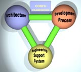
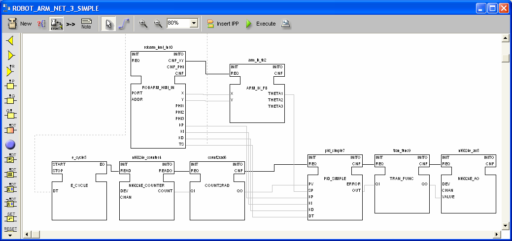
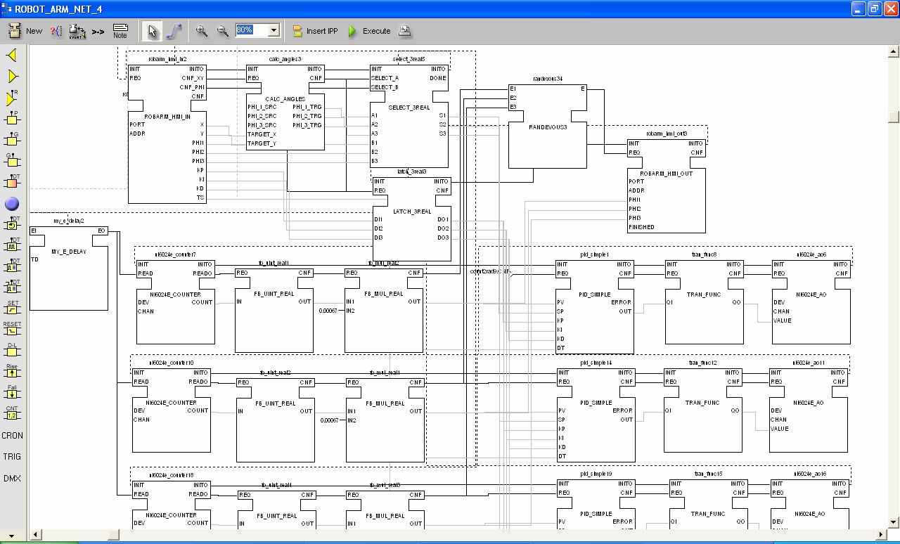
 The control application Each link of the simplified robotic arm can be controlled separately. The PID based control application block diagram for the control of a single link is shown bellow. 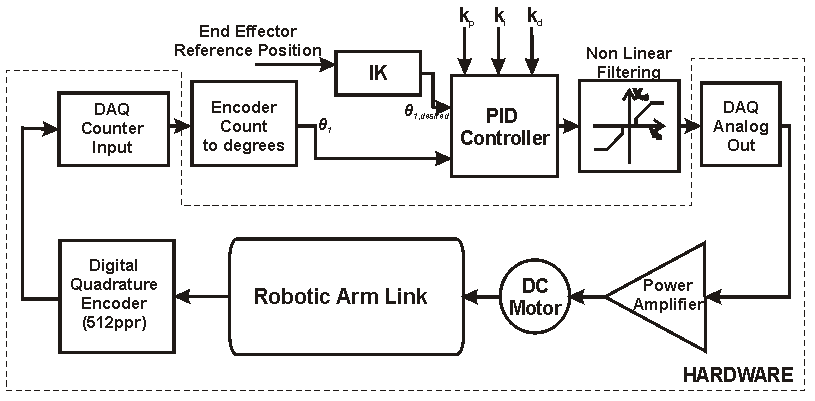 Developing the FB-based control application The above application is easily transformed to an appropriate FB network (see animation below).  Constructing FB types Corfu FBDK was used to define the FB types that are required for the development of the Robotic arm control application. However, any other IEC61499 compliant ESS, such as Archimedes ESS, can be used to define FB types. As an example the PID FB type that was used in this case study is given below: 1. PID_SIMPLE FB type graphical representation 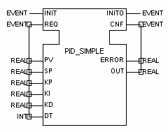 2. PID_SIMPLE FB type XML specification Constructing the FB network diagram Corfu ESS was utilized for the development of the FB network diagram. A first draft FB network diagram and the complete Function Block network diagram of the control application are given.
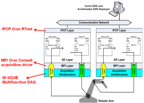
Both PCs are running the RTAI-AXE
FB execution environment that was developed over RTAI
Linux real-time OS.
For the MPI layer of the RTAI-AXE the comedi acquisition device
driver is used.
The IPCP layer of the RTAI-AXE is
implemented on top of RTnet
(real-time Ethernet for RTAI).
Application deployment is supported by a
prototype deployer of
Archimedes System
Platform.
Comming soon...
|
|
![]()
![]()
![]()
![]()
![]()
![]()
![]()
![]()
![]()
2001,2007 Software Engineering Group | Electrical & Computer Engineering | University of Patras | last Updated:11/1/2012
![]()
![]()
![]()
![]()
![]()
![]()
![]()
![]()
![]()
![]()