![]()
![]()
![]()
![]()
![]()
![]()

![]()
![]()
![]()
![]()
![]()
|
The FESTO MPP Case-Study
This case study was done in close cooperation with the university of Helsinki, Information & computer systems in automation department.
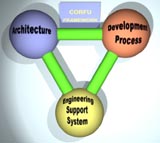
Introduction 1. IEC61499 compliant FB execution environment (J2SE-AXE) [1], 2. tool infrastructure (CORFU ESS and Archimedes System Platform) [2][3] and 3. development process, the FESTO MPP example application was developed.
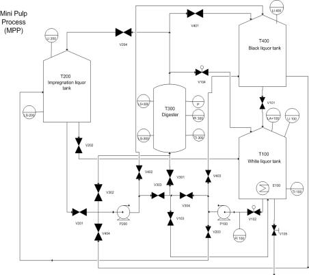
FESTO Mini Pulp Process
Figure 1. The schematic diagram of Festo MPP system.
The development of the control application was achieved using the CORFU ESS and Archimedes System Platform. The UML design diagrams were constraycted using IBM ROSE but any other UML CASE tool can be used.
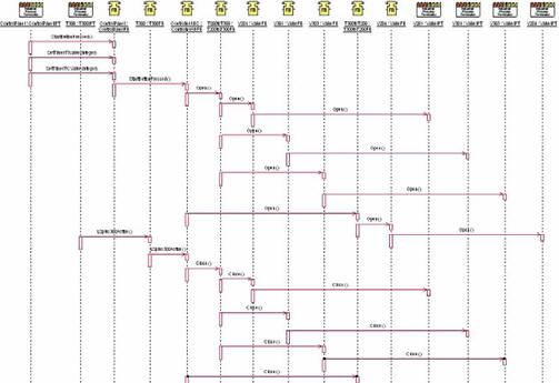
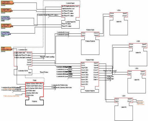
Figure 2. Example Object Interaction Diagram for Festo MPP UML diagrams were imported into Corfu fbdk and transformed to equivalent IEC61499 design diagrams (FB types and FB network diagrams). Figure 3 presents an example FB network diagram that was automatically generated by the Corfu transformation facility manager.
Figure 3. FB Network in Corfu FBDK In order to debug and demonstrate the Festo MPP control application a simulator was created, using a tcp socket interface to interact with the control application. The connection interface was build to be as close as possible with the physical process connection interface (which uses the CAN Open interface). [1] K. Thramboulidis1, S. Sierla, N. Papakonstantinou, K. Koskinen, "An IEC 61499 Based Approach for Distributed Batch Process Control", INDIN 07[2] K. Thramboulidis and C. Tranoris, “Developing a CASE Tool for Distributed Control Applications”, The International Journal of Advanced Manufacturing Technology, Volume 24, Number 1-2, July 2004, pages 24-31, Springer-Verlag. [3] K. Thramboulidis, D. Perdikis, S. Kantas, “Model Driven Development of Distributed Control Applications”, The International Journal of Advanced Manufacturing Technology, Springer-Verlag,
Under construction |
|
![]()
![]()
![]()
![]()
![]()
![]()
![]()
![]()
![]()
2001,2007 Software Engineering Group | Electrical & Computer Engineering | University of Patras | last Updated:11/1/2012
![]()
![]()
![]()
![]()
![]()
![]()
![]()
![]()
![]()
![]()