|
Small Industrial Simulation and Testing Platform(SISTEP)
SISTEP was developed to demonstrate the applicability of the CORFU development process
that is supported by CORFU ESS.
Small metal pots come to a conveyer. A sensor sends a signal and the
pot stops in front of an oblique conveyer, which loads the pot with
material. Then the conveyor moves the pot and it stops again when
the pot is in front of a
robot arm. A sensor informs the system to weight the pot and if the weight is wrong the
arm gets the pot and puts it to another bin otherwise it is
forwarded for recyclying.A small
control panel is used to control in manual mode the parts of the
mechanical process (arm,
conveyers, ...).
The picture below displays the controlled mechanical process.
|
|
|
| |
The figure
present the mechanical process of the SISTEP system. The main parts the SISTEP
mechanical process are hightlighed :
- 3 conveyers,
- the control panel,
- the controllers and
- the robot arm.
The term Industrial Process Terminators (IPTs) is used in
the CORFU development process to refer the mechanical parts of
the controlled process. The picture displays the actuators of SISTEP.
Sensors and actuators are used to have access to what is
called Industrial Process Parameters (IPPs) in CORFU development process.
- M1, M2, M3 servomotors that move the conveyers.
- M4 motor open/close the arm.
- M5 motor moves the arm up/down .
- M6 servomotor moves the arm left/right.
- Led1 lights when object in front of Conveyer 3.
- Led2 lights when object in front of Arm.
- Led3 light when object has w wrong wheight.
This picture displays the sensors of SISTEP.
- S2 is used for object in front of Conveyer 3.
- S4 is used for object in front of Arm.
- S5 senses that arm is colsed with object.
- S6 arm is open.
- S7 arm is down.
- S8 arm is up.
The buttons of the control panel are used to reset/start/stop the application and put it to Auto or Manual operation. In manual operation the other buttons are used to control the conveyers and the arm.
The figure displays the configuration of SISTEP. Actually 2 PCs are playing the role of controllers, executing the Function Block applications. CORFU ESS is used to design the
control application and the system layer model and distribute
the control application components to the system layer devices. RTAI-AXE
is used to load the FB types, create FB instances and their
event and date connections, and execute the control application. The System Layer diagram in CORFU ESS. Notice how
the way that the devices are displayed. For each device an Internal Device Diagram (IDD)
is creared. IDD makes the mapping between process parameters and FB based application. The IDD usually is shipped from the hardware vendor and encapsulates the complexities of the data transformation. Here boolean data for example in Byte0 are converted to events like ArmMoveDown. Analysis and design of the application, using ROSE. We have created Use Case and Interaction diagrams, that later are automatically transformed from CORFU FBDK
to Function Block diagrams. The figure
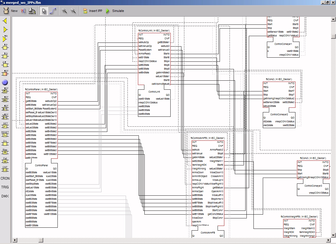
presents the final control application as a network of
interconnected FB instances. These FBs are distributed to the
system layer devices. The figure
presents ControlUnit and the ArmUnit BF types that have being
defined for the SISTEP control application. The designed FB
network is executed in the CORFU ESS for verification. The built-in runtime environment
allows such a design time execution. The validation of the FB networks is
done through the animation of the model. |
 Download a video of the
application here. (.avi 15MB 160x120) Download a video of the
application here. (.avi 15MB 160x120)
Download a video of the
application here. (.mpg 6MB 320x240)
The system is controlled by two systems based on
Parallax's
controllers and BASIC Stamp modules. The controllers are connected via RS232 to a PC. The
Function Block based application runs on
RTAI-AXE on a
real-time Linux
platform. Service Interface function blocks are used to map values
from the process to the Function Block diagrams.
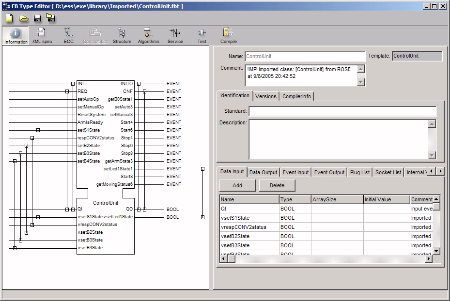
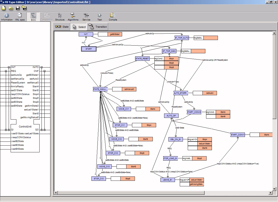
The following pictures display for example the ControlUnit
function block type. Click on any image to enlarge.
 |
 |
 |
ControlUnit Interface |
ControlUnit ECC |
The Function Block diagram |
|